Полная версия этой страницы: АЭС Фукусима
Страницы: 1, 2, 3, 4, 5, 6, 7, 8, 9, 10, 11, 12, 13, 14, 15, 16, 17, 18, 19, 20, 21, 22, 23, 24, 25, 26, 27, 28, 29, 30, 31, 32, 33, 34, 35, 36, 37, 38, 39, 40, 41, 42, 43, 44, 45, 46, 47, 48, 49, 50, 51, 52, 53, 54, 55, 56, 57, 58, 59, 60, 61, 62, 63, 64, 65, 66, 67, 68, 69, 70, 71, 72, 73, 74, 75, 76, 77, 78, 79, 80, 81, 82, 83, 84, 85, 86, 87, 88, 89, 90, 91, 92, 93, 94, 95, 96, 97, 98, 99, 100, 101, 102, 103, 104, 105, 106, 107, 108, 109, 110, 111, 112, 113, 114, 115, 116, 117, 118, 119, 120, 121, 122, 123, 124, 125, 126, 127, 128, 129, 130, 131, 132, 133, 134, 135, 136, 137, 138, 139, 140, 141, 142, 143, 144, 145, 146, 147, 148, 149, 150, 151, 152, 153, 154, 155, 156, 157, 158, 159, 160, 161, 162, 163, 164, 165, 166, 167, 168, 169, 170, 171, 172, 173, 174, 175, 176, 177, 178, 179, 180, 181, 182, 183, 184, 185, 186, 187, 188, 189, 190, 191, 192, 193, 194, 195, 196, 197, 198, 199, 200, 201, 202, 203, 204, 205, 206, 207, 208, 209, 210, 211, 212, 213, 214, 215, 216, 217, 218, 219, 220, 221, 222, 223, 224, 225, 226, 227, 228, 229, 230, 231, 232, 233, 234, 235, 236, 237, 238, 239, 240, 241, 242, 243, 244, 245, 246, 247, 248, 249, 250, 251, 252, 253, 254, 255, 256, 257, 258, 259, 260, 261, 262, 263, 264, 265, 266, 267, 268, 269, 270, 271, 272, 273, 274, 275, 276, 277, 278, 279, 280, 281, 282, 283, 284, 285, 286, 287, 288, 289, 290, 291, 292, 293, 294, 295, 296, 297, 298, 299, 300, 301, 302, 303, 304, 305, 306, 307, 308, 309, 310, 311, 312, 313, 314, 315, 316, 317, 318, 319, 320
свой - не сразу, и зависит от того, насколько свежие сборки вверху
Цитата(papa4iter @ 6.11.2013, 16:57) 
Судя по снимку на стр 11 не все сборки в идеальном состоянии...
Снимок на стр 11 показывает результаты *теста*. "A collision test has been conducted, simulating falls of debris onto fuel".
QUOTE(papa4iter @ 6.11.2013, 21:57)
Судя по снимку на стр 11 не все сборки в идеальном состоянии... интересно, это может быть следствием опускания уровня воды в бассейне? или просто что-либо сильно ударило сверху?
Я так понял, это они стокилограмовую хрень с пятиметровой высоты на сборку кидали. И смотрели что получится. Дикари-с ©
http://photo.tepco.co.jp/library/131030_02e/131030_01-e.pdf (стр.12)
QUOTE
Falling of an 100 kg stone from the height of 5 m as an extreme case.
Карта дебриса (стр.4) тут: http://www.tepco.co.jp/nu/fukushima-np/han...130826_02-j.pdf
Цитата(armadillo @ 7.11.2013, 10:46)
свой - не сразу, и зависит от того, насколько свежие сборки вверху
Дык сборки в один ряд стоят.(на одном уровне) разве нет.?
Так же на мой взгляд, о том, что пар с водородом пришел из 3 (может даже частично и 2 блока), указывает его радиоактивность.
То есть, еще 14 и 13 марта они уже не могли войти в 4 блок из-за наличия высоких доз и пара в всем помещении.
Если бы пар был только с БВ, то его радиоактивность была бы не велика до момента пока не начнут повреждаться ТВЭЛЫ. А если бы они были бы (ТВЭЛЫ) раскрыты еще 14 вечером, то там бы точно был 3.14 ец к утру 15 марта.
QUOTE(armadillo @ 7.11.2013, 11:46)
свой - не сразу, и зависит от того, насколько свежие сборки вверху
Ужасы Вы какие пишите! Вы пошутили, а народ подумает и правда, что там в восемь этажей, сборки на голове друг у друга стоят.
ок, каюсь, такие картинки принял за многоэтажность
http://www.atomic-energy.ru/files/images/2...610x%5B2%5D.jpg
http://www.atomic-energy.ru/files/images/2...610x%5B2%5D.jpg
QUOTE(anarxi @ 7.11.2013, 12:11)
Дык сборки в один ряд стоят.(на одном уровне) разве нет.?
Так же на мой взгляд, о том, что пар с водородом пришел из 3 (может даже частично и 2 блока), указывает его радиоактивность.
То есть, еще 14 и 13 марта они уже не могли войти в 4 блок из-за наличия высоких доз и пара в всем помещении.
Если бы пар был только с БВ, то его радиоактивность была бы не велика до момента пока не начнут повреждаться ТВЭЛЫ. А если бы они были бы (ТВЭЛЫ) раскрыты еще 14 вечером, то там бы точно был 3.14 ец к утру 15 марта.
Ну всякие чудеса, конечно, встречаются. Просто я не могу себе представить, что водород из 3 бл., пройдя по воздуховодам и дойдя практически до венттрубы, вдруг опомнился, не пошел вверх, в венттрубу, а развернулся и ринулся зачем-то в блок 4. Он же не сперматозоид, такие кренделя выписывать.
ну если вентрубу уже к тому времени заблокировало каким-нибудь обломком...
^^
Да там без пол-литры не разобраться. Вот что по этому поводу думает ТЕПКО:

Да там без пол-литры не разобраться. Вот что по этому поводу думает ТЕПКО:
QUOTE(armadillo @ 7.11.2013, 12:24)
ну если вентрубу уже к тому времени заблокировало каким-нибудь обломком...
Ну обломок, он же не презерватив. Вряд ли уж герметично заблокировало. Ну, ладно, я не настаиваю, это просто записки сумасшедшего скопировал.
Цитата(Nut @ 7.11.2013, 11:21)
Ну всякие чудеса, конечно, встречаются. Просто я не могу себе представить, что водород из 3 бл., пройдя по воздуховодам и дойдя практически до венттрубы, вдруг опомнился, не пошел вверх, в венттрубу, а развернулся и ринулся зачем-то в блок 4. Он же не сперматозоид, такие кренделя выписывать.
Ну, Вы же доктор, Вы должны знать, что больному лекарство можно вводить , как перорально, так и ректально.
А там разных ректальных каналов (подземные кабельные ) очень много, есть даже такие которые проходят сквозь все блоки.
QUOTE(anarxi @ 7.11.2013, 12:34)
Ну, Вы же доктор, Вы должны знать, что больному лекарство можно вводить , как перорально, так и ректально.
А там разных ректальных каналов (подземные кабельные ) очень много, есть даже такие которые проходят сквозь все блоки.
А там разных ректальных каналов (подземные кабельные ) очень много, есть даже такие которые проходят сквозь все блоки.
Есть указанные Вами каналы, но через них запулить водород, это то же самое, что гланды лечить известным способом. Теоретически наверное можно, но сложно.
http://mi3ch.livejournal.com/2416583.html
а это было?
а это было?
Цитата(Nut @ 7.11.2013, 11:39)
Есть указанные Вами каналы, но через них запулить водород, это то же самое, что гланды лечить известным способом. Теоретически наверное можно, но сложно.
Учитывая, что на входах в машзалы( в частности в 1 блоке) уровни излучения были в несколько сот рентген, то можно предположить, что часть водорода вышла в общий машзал 3-4 блоков и по вентиляции могла попасть обратно в 4 блок.
Так же до сих пор в подвале, где находится тор 4 блока стоит вода, то есть все подземные коммуникации тоже абсолютно не герметичны.
Ну и ГО 4 блока японцы усиленно обходят стороной, тоже какое то "темное информационное пятно".
armadillo
Цитата
http://mi3ch.livejournal.com/2416583.html
а это было?
а это было?
Ну, скажем так, не новая новость, насчет здесь , не знаю.
Цитата
Учитывая, что на входах в машзалы( в частности в 1 блоке)
Уточнение,
под входами подразумеваются места в которых проходят трубы с паром от реакторов.

QUOTE(anarxi @ 7.11.2013, 14:51)
Учитывая, что на входах в машзалы( в частности в 1 блоке) уровни излучения были в несколько сот рентген, то можно предположить, что часть водорода вышла в общий машзал 3-4 блоков и по вентиляции могла попасть обратно в 4 блок.
Так же до сих пор в подвале, где находится тор 4 блока стоит вода, то есть все подземные коммуникации тоже абсолютно не герметичны.
Ну и ГО 4 блока японцы усиленно обходят стороной, тоже какое то "темное информационное пятно".
Так же до сих пор в подвале, где находится тор 4 блока стоит вода, то есть все подземные коммуникации тоже абсолютно не герметичны.
Ну и ГО 4 блока японцы усиленно обходят стороной, тоже какое то "темное информационное пятно".
я почти уверен, что стопорные были закрыты, а скорее всего и ГПЗ и БЗОК и что там у них еще. Наличие единого машзала еще не говорит, что контура разных блоков связаны между собой. Не крупный специалист, но уверен, что это почти исключено. Ну там КСН, может еще что-то, но все это не пути перетекания водорода с блока на блок. Машзал, кстати, тоже не взорвался. Да и вентиляция, я уверен, разная - в машзале и на блоке. А по подземным каналам, это вообще исключено. Вот вода, наверное может, а водород вниз не полезет. Фигня это все. Не верится, что блоки так сильно связаны между собой. Только одна достойная труба - вытяжная вентиляция. Но там венттруба (уже писал).
Цитата(Nut @ 7.11.2013, 19:34)
... Машзал, кстати, тоже не взорвался. Да и вентиляция, я уверен, разная - в машзале и на блоке. А по подземным каналам, это вообще исключено. Вот вода, наверное может, а водород вниз не полезет. Фигня это все. Не верится, что блоки так сильно связаны между собой. Только одна достойная труба - вытяжная вентиляция. Но там венттруба (уже писал).
Полностью поддерживаю. Как мне представляется, при интенсивном стравливании среды из контаймента третьего блока, в вент трубу в первую очередь
Цитата(RocketMan @ 7.11.2013, 12:51)
Снимок на стр 11 показывает результаты *теста*. "A collision test has been conducted, simulating falls of debris onto fuel".
нда... проглядел я слово "симуляция"
Цитата(eNeR @ 7.11.2013, 12:54)
Я так понял, это они стокилограмовую хрень с пятиметровой высоты на сборку кидали. И смотрели что получится. Дикари-с ©
http://photo.tepco.co.jp/library/131030_02e/131030_01-e.pdf (стр.12)
Карта дебриса (стр.4) тут: http://www.tepco.co.jp/nu/fukushima-np/han...130826_02-j.pdf
http://photo.tepco.co.jp/library/131030_02e/131030_01-e.pdf (стр.12)
Карта дебриса (стр.4) тут: http://www.tepco.co.jp/nu/fukushima-np/han...130826_02-j.pdf
Спасибо! понятно. конечно, что мусор в БВ упал во время взрыва на 4-м блоке, а не до него... то есть, если какие-то сборки повеждены - то вследствие взрыва, а не повреждения вызвали взрыв...
Цитата(anarxi @ 7.11.2013, 13:11)
Дык сборки в один ряд стоят.(на одном уровне) разве нет.?
Так же на мой взгляд, о том, что пар с водородом пришел из 3 (может даже частично и 2 блока), указывает его радиоактивность.
То есть, еще 14 и 13 марта они уже не могли войти в 4 блок из-за наличия высоких доз и пара в всем помещении.
Если бы пар был только с БВ, то его радиоактивность была бы не велика до момента пока не начнут повреждаться ТВЭЛЫ. А если бы они были бы (ТВЭЛЫ) раскрыты еще 14 вечером, то там бы точно был 3.14 ец к утру 15 марта.
Так же на мой взгляд, о том, что пар с водородом пришел из 3 (может даже частично и 2 блока), указывает его радиоактивность.
То есть, еще 14 и 13 марта они уже не могли войти в 4 блок из-за наличия высоких доз и пара в всем помещении.
Если бы пар был только с БВ, то его радиоактивность была бы не велика до момента пока не начнут повреждаться ТВЭЛЫ. А если бы они были бы (ТВЭЛЫ) раскрыты еще 14 вечером, то там бы точно был 3.14 ец к утру 15 марта.
может быть я не точно помню, но вроде бы до 15 марта никто в машзал 4-го блока и не ходил. а 15-го там было возгорание, которое потушили за 2 часа... и ахнул он - намного познее 3-го, когда весь пар от третьего шел прямиком в атмосферу.
Цитата(LAV48 @ 7.11.2013, 19:24)
Полностью поддерживаю. Как мне представляется, при интенсивном стравливании среды из контаймента третьего блока, в вент трубу в первую очередь рванул побежал бы водород и гелий (ну если б он там был), а вот водяной пар с "гадостью" быстро бы заткнул фильтр на пути к 4 ЭБ и туда надуть чего-то существенного взрывоопасного стало сложноватос. Тем более не вероятным видится участие 1 и второго ЭБ в "надувательстве" 4го. 1 рванул свой запас за долго до "пожара" в 4 том, а 2 форточкой пользуется до сих пор, зачем ему какие-то подземные лабиринты?
Просто неясно (мне) куда делся пар и газ из тора 2 блока, при этом получается какое то временное совпадение.
Резкое падение давление в торе 2 блока и в этом же промежутке времени начало метаморфоз в 4 блоке.
Насчет перетока с 3 на 4 блок у японцев в отчете все посчитано и сравнение диаметров и сравнение длин труб.
По моему даже формулы есть какие то.
Кроме того все вентиляционные короба спецвентиляции в 4 блоке имеют следы внутренних взрывов. На 5 и 4 этажах короба полностью разворочены на 3 уже более слабые повреждения.
papa4iter
Цитата
может быть я не точно помню, но вроде бы до 15 марта никто в машзал 4-го блока и не ходил. а 15-го там было возгорание, которое потушили за 2 часа... и ахнул он - намного познее 3-го, когда весь пар от третьего шел прямиком в атмосферу.
Они пытались зайти в 4 реакторный блок, а не в машзал.
Наибольшей полнотой картины сразу после взрыва 4 блока обладают американские летчики, которые были первыми на месте пожара.
QUOTE(anarxi @ 8.11.2013, 10:24)
Просто неясно (мне) куда делся пар и газ из тора 2 блока, при этом получается какое то временное совпадение.
Резкое падение давление в торе 2 блока и в этом же промежутке времени начало метаморфоз в 4 блоке.
Насчет перетока с 3 на 4 блок у японцев в отчете все посчитано и сравнение диаметров и сравнение длин труб.
По моему даже формулы есть какие то.
Кроме того все вентиляционные короба спецвентиляции в 4 блоке имеют следы внутренних взрывов. На 5 и 4 этажах короба полностью разворочены на 3 уже более слабые повреждения.
Может и есть какие-то пути попадания водорода из одного блока в другой. Я просто их не знаю, они же в Японии, а я в Жмеринке. Совершенно незнакомый для жмеринских пациентов проект. Только есть какие-то фундаментальные вещи. Например, связь одного реактора с другим через машзал - ну очень трудно себе представить. Повторюсь, формально можно наверное найти, но реально попадание большого количества водорода - сложно представить. То же касается связей ГО. А вентиляция реальная связь, вот только хорошей картине мешает венттруба. А короба в блоке 4 по-любому разнесет. Т.к. даже если водород был свой, то он точно проник в венткороба. Тем более, что как говорят, шибера в венттрубу были открыты. А когда все взорвалось, он конечно и в венткоробах взорвался. Так что, на венткороба можно не ориентироваться. Вот на степень повреждения сверху в БВ, мне кажется - это реально, в воду падало или прямо по голове.
Путь перетока-то реальный. Вопрос в том, пойдет ли водород в закрытые помещения блока 4, если рядом открытая венттруба с тягой.
Тут есть важный момент, на который "напирают" японские доктора.
Трубы спецвентиляции с 3 и 4 блока вначале сходятся в одном узле и уже от него по одной трубе состыковывается с главным стеком.
Так вот по японским реалиям высота входа трубы спецвентиляции в 4 блоке значительно выше чем высота входа общей трубы (3 и 4 блоков) спецвентиляции в главный стек.
Соответственно чисто теоретически (если отбросить сопротивление угольных фильтров) сила тяги больше именно в трубе идущей к 4 блоку.
Картина выглядит так.
Происходит разгерметизация контаймента в 3 блоке, водород попадает в обстройку 3 блока и начинает искать выход наружу.
Двери в здание закрыты, единственный путь из темницы это спецвентиляция.
Водород начинает перемещаться по вентиляционным коробам в сторону выхода.
Попадает в трубу и начинает путешествие в сторону главного стека, доходит до тройника и там по японским расчетам сила тяги в сторону 4 блока больше так как конечный выход из трубы выше относительно уровня ОР нежели в главном стеке.
Как то так я понял.
QUOTE(anarxi @ 8.11.2013, 14:36)
Картина выглядит так.
Происходит разгерметизация контаймента в 3 блоке, водород попадает в обстройку 3 блока и начинает искать выход наружу.
Двери в здание закрыты, единственный путь из темницы это спецвентиляция.
Водород начинает перемещаться по вентиляционным коробам в сторону выхода.
Попадает в трубу и начинает путешествие в сторону главного стека, доходит до тройника и там по японским расчетам сила тяги в сторону 4 блока больше так как конечный выход из трубы выше относительно уровня ОР нежели в главном стеке.
Как то так я понял.
Не вяжется как-то. Даже выбравшись из 3 блока водород полюбому пойдёт в вент-трубу, а не на 4-й. Тяга туда гораздо больше. Таким-же макаром из 4-го блока (ему навстречу) тянется воздух.
Не верится мне что-то.
Да и разрушения там совсем не взрывного характера.
Кипело что-то сильно.
Из второго переток скорее всего исключается - там спаренные трубы под 1-2 и 3-4 блоки, которые не пересекаются.
QUOTE(Nut @ 8.11.2013, 11:49)
Может и есть какие-то пути попадания водорода из одного блока в другой. Я просто их не знаю, они же в Японии, а я в Жмеринке. Совершенно незнакомый для жмеринских пациентов проект. Только есть какие-то фундаментальные вещи. Например, связь одного реактора с другим через машзал - ну очень трудно себе представить. Повторюсь, формально можно наверное найти, но реально попадание большого количества водорода - сложно представить. То же касается связей ГО. А вентиляция реальная связь, вот только хорошей картине мешает венттруба. А короба в блоке 4 по-любому разнесет. Т.к. даже если водород был свой, то он точно проник в венткороба. Тем более, что как говорят, шибера в венттрубу были открыты. А когда все взорвалось, он конечно и в венткоробах взорвался. Так что, на венткороба можно не ориентироваться. Вот на степень повреждения сверху в БВ, мне кажется - это реально, в воду падало или прямо по голове.
Путь перетока-то реальный. Вопрос в том, пойдет ли водород в закрытые помещения блока 4, если рядом открытая венттруба с тягой.
Путь перетока-то реальный. Вопрос в том, пойдет ли водород в закрытые помещения блока 4, если рядом открытая венттруба с тягой.
Представить любую связь через машзал?Легко.Труднее разобраться действительно ли она есть.На вашей фабрике ,например система "OUS",помните такую?Служит для испытаний ГО от общестанционных компрессоров .транзитом через машзалы .Да только у нас локализующая группа-ручная арматура,а у них?А .помимо TL22 ,вспомните про ремонтную и применяемую для испытаний TL21.А,что помешало бы проэктанту "связать" между собой эти системы?Конечно ,снабдив перемычки должным количеством необходимой арматуры.И ,цель ведь хорошая-вместо 3 локализующих групп для 3 систем,-получаем 1 локализующую группу.Выгода.Опять же "дыр" в конструкции оболочки меньше.Прочность лучше.Трассировка трубопроводов (внутри ГО) лучше.Так что представить как раз легко.Труднее узнать насколько такие представления совпадают с реальностью.
Цитата(eNeR @ 8.11.2013, 11:46)
Не вяжется как-то. Даже выбравшись из 3 блока водород полюбому пойдёт в вент-трубу, а не на 4-й. Тяга туда гораздо больше. Таким-же макаром из 4-го блока (ему навстречу) тянется воздух.
Не верится мне что-то.
Да и разрушения там совсем не взрывного характера.
Кипело что-то сильно.
Из второго переток скорее всего исключается - там спаренные трубы под 1-2 и 3-4 блоки, которые не пересекаются.
Не верится мне что-то.
Да и разрушения там совсем не взрывного характера.
Кипело что-то сильно.
Из второго переток скорее всего исключается - там спаренные трубы под 1-2 и 3-4 блоки, которые не пересекаются.
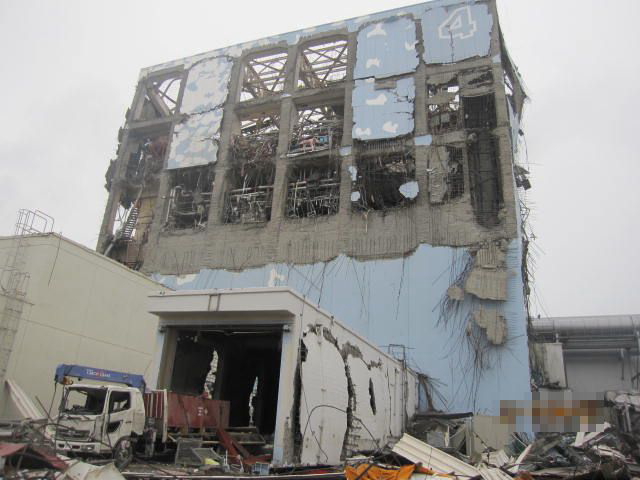
Это хорошую Вы фотку приложили, неясно из-за чего такие разрушения в шлюзе на 1 этаже, японцы не очень любят этот ракурс.
По поводу труб вентиляции, там их очень много, некоторые проходят от 1-2 блока и идут в здание рядом с 4 блоком.
(штатное здание переработки твердых радиоотходов) есть и другие.
То, что я описал с перетоком, по спецвентиляции это видение японцев.
они предполагают , что некоторая часть, около 25% прошла таким образом.
Цитата(сергей @ 8.11.2013, 12:06)
Так что представить как раз легко.Труднее узнать насколько такие представления совпадают с реальностью.
У меня есть схема спецвентиляции с амеровского БВР, понять мне её конечно тяжело. но труб там дох..я
Говорят, у джапов все намного запущенней.
QUOTE(сергей @ 8.11.2013, 13:06)
Представить любую связь через машзал?Легко.Труднее разобраться действительно ли она есть.На вашей фабрике ,например система "OUS",помните такую?Служит для испытаний ГО от общестанционных компрессоров .транзитом через машзалы .Да только у нас локализующая группа-ручная арматура,а у них?А .помимо TL22 ,вспомните про ремонтную и применяемую для испытаний TL21.А,что помешало бы проэктанту "связать" между собой эти системы?Конечно ,снабдив перемычки должным количеством необходимой арматуры.И ,цель ведь хорошая-вместо 3 локализующих групп для 3 систем,-получаем 1 локализующую группу.Выгода.Опять же "дыр" в конструкции оболочки меньше.Прочность лучше.Трассировка трубопроводов (внутри ГО) лучше.Так что представить как раз легко.Труднее узнать насколько такие представления совпадают с реальностью.
ОUS - ремонтная, открывается крайне редко и исключительно на одном из блоков. И перед открытием на одном из блоков, все остальные бегут и проверяют закрытие на других. Так мне пациенты рассказывали. Так что, через подобную систему ничего никуда не перетекает. Ни одна из TL одного блока не имеет связи с другим. Домыслы "а что мешает" - это все же фантазии. На Украине вот, например, до такого слава Богу не додумались. А японы, думаю не глупее. Поэтому, я имел ввиду, что физически трубы между блоками есть, но совершенно невероятно, чтобы они были не отключены (работающий блок от ремонтируемого). Да еще и одноконтурные блоки.
QUOTE(anarxi @ 8.11.2013, 13:29)
У меня есть схема спецвентиляции с амеровского БВР, понять мне её конечно тяжело. но труб там дох..я
Даже не пытайтесь. Не зная по месту географии, характеристик, режимов работы и особенностей, даже не пытайтесь. Госпитализируют уже через час.
QUOTE(Nut @ 8.11.2013, 13:54)
ОUS - ремонтная, открывается крайне редко и исключительно на одном из блоков. И перед открытием на одном из блоков, все остальные бегут и проверяют закрытие на других. Так мне пациенты рассказывали. Так что, через подобную систему ничего никуда не перетекает. Ни одна из TL одного блока не имеет связи с другим. Домыслы "а что мешает" - это все же фантазии. На Украине вот, например, до такого слава Богу не додумались. А японы, думаю не глупее. Поэтому, я имел ввиду, что физически трубы между блоками есть, но совершенно невероятно, чтобы они были не отключены (работающий блок от ремонтируемого). Да еще и одноконтурные блоки.
Конечно "ремонтная" ,кто спорит то...Только представьте ,что оснащена не "ручной" арматурой,а "приводной".И шкаф,где находятся БУЗы и АДП "неправильно" распитался.(По аналогии с нашими ,скажем сначала "вылетело" питание 15В,а только затем 24В).А уж про возможные решения и всевозможные "перемычки" трубопроводные ..фантазии не хватит.Особенно этой болезни подвержены многоблочные станции.Могу напомнить Вам случай ,когда вода спецпрачечной из за подобной "перемычки" попала в баки чистого дистиллата.И в аккурат подоспела к выводу блока на МКУ после ремонта..
QUOTE(сергей @ 8.11.2013, 14:10)
Конечно "ремонтная" ,кто спорит то...Только представьте ,что оснащена не "ручной" арматурой,а "приводной".И шкаф,где находятся БУЗы и АДП "неправильно" распитался.(По аналогии с нашими ,скажем сначала "вылетело" питание 15В,а только затем 24В).А уж про возможные решения и всевозможные "перемычки" трубопроводные ..фантазии не хватит.Особенно этой болезни подвержены многоблочные станции.Могу напомнить Вам случай ,когда вода спецпрачечной из за подобной "перемычки" попала в баки чистого дистиллата.И в аккурат подоспела к выводу блока на МКУ после ремонта..
Ну вот опять - "представьте, если бы было не так, как сейчас...". А вода попала со спецкорпуса, а не с другого блока. И не из ГО, тем более. И не в ГО конечно. Ну еще таракан может в суп попасть. Я не возражаю, что может что-то куда-то попасть. Просто вряд ли из помещений одного блока в другой, тем более при одноконтурной схеме. Ладно, в общем суть понятна.
Цитата
то некоторая часть, около 25% прошла таким образом.
Эта фраза однозначно переводится с бюрократического "мы нашли отмазу и будем ей прикрываться"
И чуть добавлю.А почему складывается мнение ,что даже при открытых шиберах штатной линии вентиляции газ,воздух должен уходить в трубу?Это не совсем так.Или совсем не так.При нормальной работе штатной системы вентиляции только работа мощных "вентиляторов" обеспечит такой путь.Преодолев сопротивление аэрозольных и йодных фильтров.Даже при наличии избыточного давления в оболочке ,без работы агрегатов это достаточно сложно...Уж больно сопротивления велики.Поэтому версия японцев имеет право на жизнь.
Нашел видео steam rising-a: http://www.telegraph.co.uk/news/worldnews/...om-the-air.html
На 14 число судя по спутниковым снимкам 4-й блок себя нормально чуствовал: http://earp.cga.harvard.edu/files/japan/Da...lobe_report.pdf
Что творилось в прессе на тот момент: http://web.archive.org/web/20110318052257/...1/03/78352.html
Так что я пока при своих
На 14 число судя по спутниковым снимкам 4-й блок себя нормально чуствовал: http://earp.cga.harvard.edu/files/japan/Da...lobe_report.pdf
Что творилось в прессе на тот момент: http://web.archive.org/web/20110318052257/...1/03/78352.html
Так что я пока при своих
http://earp.cga.harvard.edu/files/japan/Da...lobe_report.pdf
Качество конечно плохое, но вроде пристройка - шлюз на 4 блоке еще 12 числа цела.
Стена без трещин.
На снимке от 14 марта между машзалом и реакторным зданием 4 блока. виден пар или облака, как кому хочется видеть.
В общем пристройка меня больше всего интересует, если она повреждена внутренним взрывом, тогда водород шел просто из земли, или из-под земли.
QUOTE(anarxi @ 8.11.2013, 10:24)
Просто неясно (мне) куда делся пар и газ из тора 2 блока, при этом получается какое то временное совпадение.
Резкое падение давление в торе 2 блока и в этом же промежутке времени начало метаморфоз в 4 блоке.
...................
Резкое падение давление в торе 2 блока и в этом же промежутке времени начало метаморфоз в 4 блоке.
...................
Скорее всего, это просто совпадение. Поскольку на схеме внешних коммуникаций блоков 2 – 4 и ГО и тор имеют штатный выход в вентиляционную трубу. Линии 24 и 25 на схеме.

QUOTE(Nut @ 8.11.2013, 11:49)
.....................................
А вентиляция реальная связь, вот только хорошей картине мешает венттруба. А короба в блоке 4 по-любому разнесет. Т.к. даже если водород был свой, то он точно проник в венткороба. Тем более, что как говорят, шибера в венттрубу были открыты. А когда все взорвалось, он конечно и в венткоробах взорвался. Так что, на венткороба можно не ориентироваться. Вот на степень повреждения сверху в БВ, мне кажется - это реально, в воду падало или прямо по голове.
Путь перетока-то реальный. Вопрос в том, пойдет ли водород в закрытые помещения блока 4, если рядом открытая венттруба с тягой.
QUOTE
LAV48 @ 7.11.2013, 19:24
Как мне представляется, при интенсивном стравливании среды из контаймента третьего блока, в вент трубу в первую очередь рванул побежал бы водород и гелий (ну если б он там был), а вот водяной пар с "гадостью" быстро бы заткнул фильтр на пути к 4 ЭБ и туда надуть чего-то существенного взрывоопасного стало сложноватос.
Как мне представляется, при интенсивном стравливании среды из контаймента третьего блока, в вент трубу в первую очередь рванул побежал бы водород и гелий (ну если б он там был), а вот водяной пар с "гадостью" быстро бы заткнул фильтр на пути к 4 ЭБ и туда надуть чего-то существенного взрывоопасного стало сложноватос.
Теоретически возможность натекания значительного количества «чего-то там» из б3 в б4 существует.
Вот фрагмент участка вентсистемы между б3 и б4. Как видно на снимке патрубки из б3 и б4 входят в общую магистраль прямо напротив друг друга. Разрушения магистрали из б3 носят явно механический характер, то есть в самой трубе за пределами б3 взрывов не было. Следовательно, она могла быть разрушена только после взрыва б3, а до этого времени исправно работала.

Кроме того, магистраль состоит из участков небольшой длины, явно меньше 65 метров и диаметром явно больше 20 мм. Наверняка существует некая запорная и предохранительная арматура.
Это к тому, что налицо идеальные условия для того, чтобы в вентиляционной системе блока 3 смесь «чего-то там» оказалась под повышенным давлением.
В результате волна детонации пойдёт по газу с повышенным давлением, причём гореть она не будет. По некоторым данным давление в такой трубе может возрасти в 240 раз, по сравнению с начальным.
При таких условиях тяга вытяжной трубы, скорее всего, «перевернётся», а смесь в трубе прямиком пойдёт в блок 4.
А в остальном Вы правы, вероятность штука тонкая…
QUOTE(armadillo @ 8.11.2013, 14:29)
Эта фраза однозначно переводится с бюрократического "мы нашли отмазу и будем ей прикрываться"
В общем-то, ничего удивительного в этом нет – это обычная тактика поведения в рискованных ситуациях…
http://www.youtube.com/watch?v=y4reARQhJ6c
Кому же хочется оказаться в ситуации подобной вот этой.
http://www.youtube.com/watch?v=xytEaQAwuRY
Renegade, а вот по-поводу шлюза на 1 этаже 4 блока какие мысли? Отчего его "так"?
Цитата(renegade1951 @ 8.11.2013, 16:39)
Теоретически возможность натекания значительного количества «чего-то там» из б3 в б4 существует.
Вот фрагмент участка вентсистемы между б3 и б4. Как видно на снимке патрубки из б3 и б4 входят в общую магистраль прямо напротив друг друга
Кроме того, магистраль состоит из участков небольшой длины, явно меньше 65 метров и диаметром явно больше 20 мм. Наверняка существует некая запорная и предохранительная арматура.
…
Та труба по которой шел переток газов на Вашем снимке не видна.
Та труба намного меньшего диаметра и практически не видна под этими большими и толстыми.
Если присмотреться то с левой стороны за большой трубой виднеется тонкая трубочка( хотя её диаметр 300 мм вроде) вот то она.
QUOTE(eNeR @ 8.11.2013, 17:52)
Renegade, а вот по-поводу шлюза на 1 этаже 4 блока какие мысли? Отчего его "так"?
Если судить по снимку выше, то внутри этой халабуды произошёл взрыв. А вот что там такое бумкнуло и как оно там оказалось - это вопрос дискуссионный. По одному снимку такой вывод сделать очень трудно. Со всем уважением, коллега.
Цитата(renegade1951 @ 8.11.2013, 18:39)
В результате волна детонации пойдёт по газу с повышенным давлением, причём гореть она не будет. По некоторым данным давление в такой трубе может возрасти в 240 раз, по сравнению с начальным.
При таких условиях тяга вытяжной трубы, скорее всего, «перевернётся», а смесь в трубе прямиком пойдёт в блок 4.
А в остальном Вы правы, вероятность штука тонкая…
При таких условиях тяга вытяжной трубы, скорее всего, «перевернётся», а смесь в трубе прямиком пойдёт в блок 4.
А в остальном Вы правы, вероятность штука тонкая…
Каков тогда будет объём смеси, реально способный поступить в обстройку 4 блока?
P.S. Расположение врезок трубопроводов под острым углом в общий коллектор вытяжной трубы при таком "выстреле" создал бы дополнительную тягу из вентиляции 4 ЭБ. Скорее натекание более заметно было б при длительном удержании повышенного давления, что при открытой трубе такого диаметра, мягко говоря, затруднительно.
QUOTE(anarxi @ 8.11.2013, 18:13)
Та труба по которой шел переток газов на Вашем снимке не видна.
Та труба намного меньшего диаметра и практически не видна под этими большими и толстыми.
Если присмотреться то с левой стороны за большой трубой виднеется тонкая трубочка( хотя её диаметр 300 мм вроде) вот то она.
Та труба намного меньшего диаметра и практически не видна под этими большими и толстыми.
Если присмотреться то с левой стороны за большой трубой виднеется тонкая трубочка( хотя её диаметр 300 мм вроде) вот то она.
Собственно говоря, обсуждалась возможность перетекания "чего-то там" по вентиляции минуя вытяжную трубу....
Других магистралей, связанных с трубой, там как бы и нет. Вот Вам панорама с другой строны.

На снимке Ваша тоненькая трубочка есть, но с вытяжкой она не связана, по крайней мере на улице.
Какую именно маленькую трубочку имели ввиду японцы трудно сказать, но если её диаметр больше 20 мм, то все приведенные выше соображения остаются в силе.
С уважением...


QUOTE(renegade1951 @ 8.11.2013, 17:39)
Наверняка существует некая запорная и предохранительная арматура.
Это к тому, что налицо идеальные условия для того, чтобы в вентиляционной системе блока 3 смесь «чего-то там» оказалась под повышенным давлением.
В результате волна детонации пойдёт по газу с повышенным давлением, причём гореть она не будет. По некоторым данным давление в такой трубе может возрасти в 240 раз, по сравнению с начальным.
При таких условиях тяга вытяжной трубы, скорее всего, «перевернётся», а смесь в трубе прямиком пойдёт в блок 4.
Предохранительной арматуры на таких воздуховодах нет.
Повысилось давление со стороны блока 3, там же и сдетонировала смесь, оторвало воздуховод от бл.3. В это время тяга перевернулась. Но смесь в этом случае пошла из трубы в дырку к блоку 3. А в сторону 4 бл. ничего все равно не пойдет. Вот и даже по такому варианту он не попадет на бл.4 (да уже нечему и попадать - водорода нет и в трубе дырка).
А в остальном Вы правы...
А кто в курсе, какой водород японцы в 4 блок приписали, который с контаймента сами травили или тот что с обстройки 3ЭБ до взрыва "перебегал" вплоть до взрыва?
С обстройки.
With regard to the pipes (Pa) that release vent gas into the outside air via the stack from the merging point of the Unit 3 SGTS pipes and Unit 4 SGTS pipes, and the Unit 4 SGTS pipes (Pb), while there is a certain error in the ratio of the effective pipe to the pipe inner diameter,
the ratio (Pa /Pb) of the effective pipe length divided by the inner diameter of Pa to Pb is approximately 1 to 3.8.
Concerning the velocity of fluid that flows from the Unit 3 SGTS
pipes into the stack side pipe through the merging point of the Unit 3 and Unit 4 SGTS pipes, and the velocity of another fluid that flows from the Unit 3 SGTS into Unit 4 SGTS pipes through the merging point above, the ratio of the velocity between the two fluids is inversely proportional to 1/2 power of the ratio (of 1 to 3.8) above and thus is approximately 2.0 to 1.0.
Moreover, the amount of inflow into pipes is determined by the product of the fluid velocity in the pipe and its cross-sectional area.
As such, the ratio of the amount of inflows of the stack side to the Unit 4 R/B side is approximately 2.6 to 1.0.
In addition, while a gravitational loss as a factor for suppression of inflow into the stack side is considered due to upward movement of the fluid following a flow into the exhaust stack , conversely, a factor for enhancement of inflow into the Unit 4 R/B is that the diameter of the pipes located in front of the SGTS filters on the second floor of the Unit 4 R/B is markedly larger and splits into A-train and B-train.
Meanwhile, a factor for suppression of inflow into the Unit 4 R/B is likely the existence of the SGTS filters.
However, even considering these factors it is still impossible to derive a factor that significantly influences the ratio of inflow into the pipes, and it would not be unnatural even if an estimated amount of at least around 25% of the fluid, that flowed into the merging points (of the Unit 3 SGTS pipes and Unit 4 SGTS pipes), flowed into the Unit 4 R/B.
Taking the above into account, and assuming that by midnight on March 15, 2011 at least approximately 800kg of hydrogen had been generated in Unit 3, even if 400kg of hydrogen had accumulated within the Unit 3 R/B, it is possible that 400kg of hydrogen flowed into the stack and Unit 4 SGTS pipes via the Unit 3 SGTS pipes once the containment vents were opened.
Assuming that 25% of this hydrogen flowed into the SGTS pipes of Unit 4, it is possible that a total of 100kg of hydrogen flowed from the Unit 4 SGTS pipes into the Unit 4 R/B.
(v) Therefore, if the air inside the Unit 4 R/B was assumed to be 30в„ѓ and the atmospheric pressure, and if approximately 74.2kg of hydrogen accumulated in a 5,000-m3 space, it would be possible for a detonation to occur within this space.
170 As such, there is ample room to state that a total of 80kg of hydrogen flowed into the Unit 4 R/B and then accumulated in a certain space, such as the west side of the fourth floor, for example, a portion of the hydrogen spread to the third and fifth floors through machinery service hatches and other passages, and then that this hydrogen caused an detonation inside the Unit 4 R/B
*According to interviews conducted with the plant manufacturer, there is one 90-degree bend in the pipes that
release vent gas into the outside air from Unit 3 R/B through the merging point between the Unit 3 SGTS pipes
and the Unit 4 SGTS pipes, and a stack. The total pipe length as converted to the straight pipe length is
143,530mm. If the length of the Unit 4 SGTS pipes, which run from the above mentioned merging point to the
merging point with the main air conditioning pipes through the second story Unit 4 R/B SGTS facilities, is the
length of the pipes, the total pipe length as converted to straight pipe length is approximately 481,256.5mm, as
there exist multiple butterfly valves, 45-degree bends, 90-degree bends, bifurcations and as the pipes near the
SGTS filter separate and run parallel between A-train and B-train
http://www.cas.go.jp/jp/seisaku/icanps/eng/03IIfinal.pdf
Кстати, хотел спросить:
на ВВЭРах в зданиях блоков тоже создают пониженное давление.??
В японских БВРах в самих зданиях в время работы блоков на мощности внутреннее давление в помещениях ниже чем на улице, так понимаю, что бы ни один беккерель не збёг.
на ВВЭРах в зданиях блоков тоже создают пониженное давление.??
В японских БВРах в самих зданиях в время работы блоков на мощности внутреннее давление в помещениях ниже чем на улице, так понимаю, что бы ни один беккерель не збёг.
В ГО - да
QUOTE(anarxi @ 8.11.2013, 18:54)
..........................
http://www.fukuleaks.org/web/?page_id=9326
http://www.fukuleaks.org/web/?page_id=9326
Собственно я Вам не оппонирую, если мои реплики были поняты именно так.
Там на станции столько магистралей, что разобраться в них могут только японцы и то, наверное, после ведра сакэ.